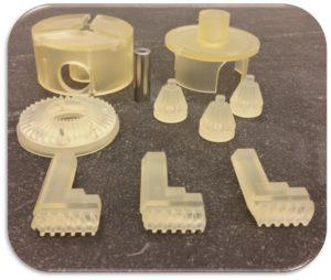
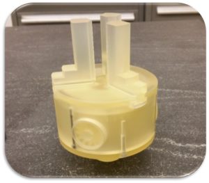
Additive Manufacturing Lab Building 77 Room 220
Contact: Willy Evans 510-486-5215
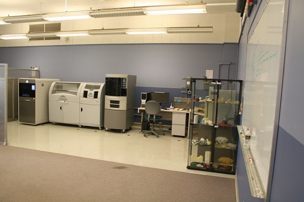
Additive Manufacturing projects are usually submitted and tracked by the use of a Web Job Order (WJO.lbl.gov). Choose “Onsite Order” under the Issue To Work Center pull down choose the “B77 Mechanical Fab Shops”.
People who are interested, can request that they be trained to use the printers. This can be requested on the WJO and usually requires about 2 hrs of on the job training while your parts are being printed. Once a person is trained on the equipment, process, and safety requirements after being added to the WPC activity they can be given access and only pay for consumables.
Printer Descriptions
ProJet 3500: MultiJet Printing (MJP)
The MJP machine uses a series of printer heads aligned with the y-axis to deposit a photopolymer resin and casting wax onto a build surface to construct a part. The build platform moves along the x-axis and the printer heads move along the z-axis resulting in print layers being uniaxial. Although the layers form a uniaxial structure, the material response in the xy-plane is relatively isotropic. Each individual material drop is about 0.075 mm (0.003 in) in diameter and approximately 0.030 mm (0.0012 in) thick allowing for fine high resolution features. Due to the printer heads moving in the z-axis rather than the build platform there is no way to purge the printer heads during printing meaning that the more material that must be deposited, the higher the risk for printer heads to become blocked and the print fails. Since the material is deposited in a fluid form and rapidly cured utilizing UV light, unless a significant fillet is applied, a lip will forms on all edges of the bottom surface and all edges become rounded on the top surface.
The ProJet is recommended for printing of functional parts that have small volumes (< 8 in3), desired tolerances no smaller than 0.25 mm (0.010 in), and in which transparency is not a concern.
Dimension Elite: Fused Deposition Modeling (FDM)
The FDM machine uses a single printer head with two extrusion nozzles to deposit the build and support material. The printer head moves in the x- and y-directions while the build platform drops in the z-direction. Each layer of the internal structure is deposited in an alternating orientation to improve material response in the xy-plane, but the layer-by-layer construction in the z-direction means that the final printed part is highly anisotropic. The layer-by-layer construction also results in ribbed surface finish corresponding to the layer thickness, 0.178 mm (0.007 in), for vertical faces and a stair step like surface finish for angle faces. Since the build platform drops in the z-direction, the extrusion nozzle can be cleaned throughout the printing process making it is possible to print parts with large volumes. The dual nozzles for the build and support material on a single print head results in a slow print process, especially for large, fully solid parts.
The Dimension Elite is recommended for printing of functional parts in which surface roughness is not a concern.
ZPrinter 650: ColorJet Printing (CJP)
The CJP machine uses five printer heads (clear, yellow, magenta, cyan, and black) to deposit a water based color binder onto a plaster based powder bed. The printer heads move in the x- and y-directions while the build platform drops in the z-direction resulting in a uniaxial internal structure corresponding to the x-direction. As a plaster based printing technique, the printed parts are highly brittle and prone to chipping; to increase the durability, a super-glue type bonding agent is applied to the part through either soaking or directed surface application. The finished parts have a very rough surface finish that can be sanded to achieve a smoother finish.
The ZPrinter is recommended for printing of prototypes where functionality and durability are low priorities.
3D- Printer
Additive Manufacturing
Cost and Time Comparison
Sample Estimate
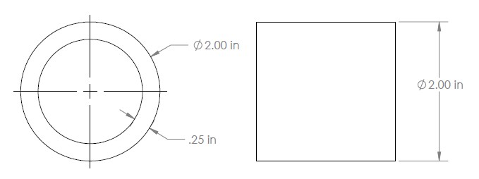
Figure 1: Simple tube for cost estimate comparison.
| ProJet 3500 (MJP) | Dimension Elite (FDM) | ZPrinter 650 (CJP) | |
| Cost Estimate | $ 95 + labor | $ 20 + labor | $ 35 + labor |
| Print Time Estimate | 17.75 hours | 7.25 hours | 2 hours |
Note: The part is estimated as being printed vertically to avoid filling the part with support material which increases cost for the ProJet 3500 and the Dimension Elite and increases the print time for the Dimension Elite.
Factors Influencing Cost and Time
Build Orientation
For the sample tube above, the print orientation has a large impact on the material cost and the print time for the ProJet and Dimension Elite. In both cases, rotating the tube so the center is along the xy-plane requires filling the center with support material whereas aligning the center with the z-axis the part remains hollow. For the Projet this will have a negligible impact on the print time since the layers are printed by a series of print heads moving along a single axis; note that this is only true based upon the height and outer diameter being equal. The print cost for the Projet is expected to significantly increase since the entire center for the part above must be filled more than doubling the volume of material used. While the Dimension Elite may not require filling the center completely, the amount of time and material necessary increases considerably since only a single line of either part or support material may be deposited at any given moment.
Unsupported Structures
While the final part may be structurally stable any overhang or unsupported feature will require the use of support material to prevent breakage during printing. For the 3D printers, an unsupported structure is any features that deviates from a vertical orientation; the sample tube above provides an example of an unsupported structure when rotated onto the round sides. The effects of unsupported structures and overhangs is the same as the discussion of the build orientation.
Quantity of Printed Parts
For the ProJet, increasing the number of parts printed causes a minor increase to print time since the largest impact on time is the height in the z-direction. Roughly the same is true for the ZPrinter though a more noticeable increase in print time can be observed due to more necessary motion by the print heads when compared to the ProJet. The Dimension Elite has a direct correlation between the print time and the number of parts printed due to the nature of the printer.
For all machines, the increase in material costs directly corresponds to the number of parts printed and may increase the labor cost due to increased time necessary for post-processing.
Material Properties
Material properties of 3D printed parts are print orientation dependent due to the layer-by-layer construction. The values provided below are the average of all orientations.
| Average of Properties | ProJet 3500 (MJP) | Dimension Elite (FDM) * | ZPrinter 650 (CJP) ** |
| Tensile Strength, Yield | 30.6 MPa (4.44 ksi) | 31 MPa (4.55 ksi) | N / A |
| Tensile Strength, Ultimate | 32.9 MPa (4.78 ksi) | 33 MPa (4.70 ksi) | 9.40 MPa (1.36 ksi) |
| Modulus of Elasticity | 1665 MPa (242 ksi) | 2200 MPa (320 ksi) | 4941 MPa (717 ksi) |
| Elongation, 0.5% Offset Yield | 2.21 % | 2 % | N / A |
| Elongation, Break | 8.53 % | 6 % | 0.299 % |
- The values provided are manufacturer specified for an ASTM D638 Type 1 specimen oriented such that the long edge is along the x-axis and the short edge is along the z-axis. No specimen testing has been done at this time to verify results.
- Note that the manufacturer reports larger strength and modulus of elasticity values.
Printer Capabilities
The table below lists each of the machine capabilities. Definition of each capability is on the next page.
| ProJet 3500 (MJP) | Dimension Elite (FDM) | ZPrinter 650 (CJP) | |
| Net Build Volume | 298 x 185 x 203 mm (11.75 x 7.3 x 8 in) * | 190 x 190 x 292 mm (8 x 8 x 12 in) | 10 x 15 x 8 in (254 x 381 x 203 mm) |
| Minimum Layer Thickness | 0.030 mm (0.00125 in) | 0.178 mm (0.007 in) | 0.10 mm (0.004 in) |
| Feature Tolerance per 25 mm | 0.15 mm (0.006 in) | 0.075 mm (0.003 in) | 0.075 mm (0.003 in) |
| Thin-walled Feature Thickness | 0.25 mm (0.010 in) | 0.65 mm (0.025 in) | 1.25 mm (0.050 in) |
| Minimum Mating Clearance | 0.075 mm (0.003 in) | ** | 0.050 mm (0.002 in) |
| Minimum Horizontal Through Hole Diameter | (0.030 in (0.75 mm) | 2.5 mm (0.1 in) | |
| Part Material | VisiJet M3 Crystal (Rigid Plastic) | ABSPlus P430(ABS) | VisiJet PXL(Plaster Base) |
| Support Material | VisiJet S300(Removable Wax) | Soluble Support (Sodium Hydroxide Soluble) | Loose powder or Printed support |
| Part Fill | Solid | Solid, Sparse (low density), and Sparse (high density) † | Solid (low density) or Solid (high density) ‡ |
| Print Color | Clear | Ivory, White, Black, Grey, Red, Blue, Olive Green, Nectarine, Yellow | Full CMYK |
- Parts exceeding a total volume of 8 in3are not recommended on the MJP machine due to material cost and increased likelihood of print failure.
- Due to the nature of the FDM printed parts, a seam forms parallel to the z-axis on the surfaces of the parts impacting the mating ability of parts. For features on the xy-plane with corners, the seam will appear along one corner reducing the impact, but for circular features without corners, the seam appears at a set orientation on the build platform.
† The part fill for the FDM machine refers to the spacing between the deposited material lines inside the part, see Figure 2.
‡ High and low density refers to the concentration of the binder in the internal structure of the printed part. Note that the default part fill is low density.
NOTE: Any blank value remaining in the table was unable to be tested due to prolonged machine downtime.
(c)(b)(a)
- Due to the nature of the FDM printed parts, a seam forms parallel to the z-axis on the surfaces of the parts impacting the mating ability of parts. For features on the xy-plane with corners, the seam will appear along one corner reducing the impact, but for circular features without corners, the seam appears at a set orientation on the build platform.

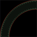
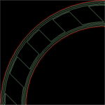
Figure 2: Close up of the nozzle path for Dimension Elite (FDM) where a) is the solid fill whose material lines touch, b) is the high-density sparse fill whose material lines have a small air gap to decrease print time with minimal strength loss, and c) is the slow density sparse fill whose material lines have a large air gap to decrease print time and produce a lightweight part.
A discussion of each machine capabilities is listed below:
- Net Build Volume: The values provided are the maximum build volume in which the printed part must be contained; parts should have a minimum clearance of 12.5 mm (0.5 in) from each build volume boundary to ensure best print quality.
- Minimum Layer Thickness: The value provided is the thickness of each printed layer and corresponds to the minimum detectable feature size printed on a plane parallel to the z-axis.
- Feature Tolerance per 25 mm: The tolerance provided is for parts and features printed normal to the xy-plane.
- Thin-walled Feature Thickness: Parts with thin-wall features smaller than the specified value may not survive the cleaning process. Features such as grooves in the xy-plane have a higher probability of survival but there is no guarantee of tolerance satisfaction of detail retention.
- Minimum Mating Clearance: For features that are mated together, the CAD model must have the minimum spacing between the two features specified in the table.
- Minimum Horizontal Through Hole Diameter: The diameter provided is for a hole constructed on the normal to the z-axis in which support material must be removed. For straight holes, the diameter maybe decreased by 0.25 mm (0.010 in).
- Part Fill: On some of the machines, the part can be printed with an array of internal structures that correspond to the final part strength and print speed.
- Print Color: On some of the machines, the part can be printed with a variety of colors. Unless specified by the designer, the color is selected by the machine operator.
